001 : Buzz Car Line-Following Toy Car
About the Buzz Car

A picture of the finished car prototype
The Buzz Car was a group project to develop a line following car kit for the Electrical and Computer Engineering (ECE) Design Fundamentals course. Given a fictional scenario, third-year undergraduate ECE students played the role of engineers hired by a toy company entrepreneur in groups of four, utilizing both hardware and software to solve the problem. The final deliverable was a prototype educational kit for K-12 classrooms that could be further developed into a marketable product to be sold.
A list of customer requirements were as follows:
- prototype was to cost no more than $100
- be able to follow a black line on a white background
- be easy to power on and begin line-following function
- output audio
- give visual feedback in the form of lights
- be battery-powered
- PCBs are easy to see
- have an aesthetic that appeals to the target audience (children)
Implementation
The Buzz Car was Formula-1 themed to appeal to the target audience and the entire system was split into four different systems:
- Motion subsystem: Controls the movement of the car using a PID closed feedback loop
- Sensing subsystem: Receives and processes the sensor data
- Output subsystem: Transmits data about the car through visual and audio
- Hardware subsystem: Sends power to the rest of the subsystems from the power source + the outer shell
- Controller "subsystem" (pseudo-subsystem): The central ESP32 microcontroller communicating with and connecting data flow between the other subsystems
PCBs were designed for each subsystem (including the controller "subsystem") to ensure the entire system was modular.
My Work on the Project
Leadership and Thorough Documentation
As the team leader, there was responsibility to ensure the team stayed on track with a weekly schedule that was created at the beginning of the semester then gradually updated as needed. Weekly notes, group todo lists, and other documentation was tracked in a lab notebook in Microsoft OneNote.
Example of a lab notebook page
Output Subsystem
The output subsystem was assigned, which mainly consists of a speaker and an LCD screen.
Thus, the two components were designed for (breadboarding, schematic, PCB design) and
tested separately. The output subsystem was separate from the main function of the car
to follow a line so a balance was kept between power usage and usability of
each main component. This led to the 16x2 LCD and PCB mount speaker to be chosen. The
LCD took more power but was larger than other screens that used less power, leading to
readability of the text. Because of this, a speaker that used less power was chosen even
if it meant limiting the audio functionality to a series of single tones.
The total components used in this subsystem are shown below:
Bill of Materials for the Output Subsystem
| Component | Quantity | Datasheet (if available) |
|---|---|---|
| 16X2 LCD | 1 | WINSTAR_WH1602B.pdf |
| 10k potentiometer | 1 | https://www.bourns.com/pdfs/3386.pdf |
| 220Ω resistor | 1 | SEI-CF_CFM.pdf |
| 330Ω resistor | 2 | SEI-CF_CFM.pdf |
| Red 5mm diameter LED | 1 | Lumimax_5DLED5RED.pdf |
| PCB mount speaker | 1 | PCBspeaker.pdf |
| NPN transistor | 1 | 2N3904-D.pdf |
| 1x2 terminal block screw connector | 4 | N/A |
| 1x3 terminal block screw connector | 1 | N/A |
LCD Screen Function
The screen acted as a visual indicator of whether the four sensors on the car detected white or black, as well as whether the car is going straight, turning right, or turning left.
Speaker Function
The speaker played a series of singular tones at different frequencies and durations
using the Arduino tone() function. While it is possible to simply write a series
of tone(), delay(), and noTone() functions to write a sequence of notes, MIDI files
could also be converted into a series of these functions easily using a website by
@TawsifTorabi, which can be checked out here.
The user would have the ability to change what is being played while the car is
moving and performing its line-following function. In the demonstration of the
prototype, the audio being played was the Georgia "Ramblin Wreck" Fight Song which was
converted from an mp4 from the official Georgia Tech Music Downloads page to a MIDI file, then to a
series of tone() functions using the tool mentioned earlier.
Breadboarding
The LCD screen was breadboarded and initially tested with the ESP32. The
LiquidCrystal library was used in the Arduino IDE. The test code printed "Hello
world" on the first row and the number of seconds that had passed since setup on
the second row.
The speaker was also breadboarded and tested for functionality, but with
an Arduino rather than an ESP32. The tone() function was used to play three
frequency tunes in a loop repeatedly, just to check for speaker function.
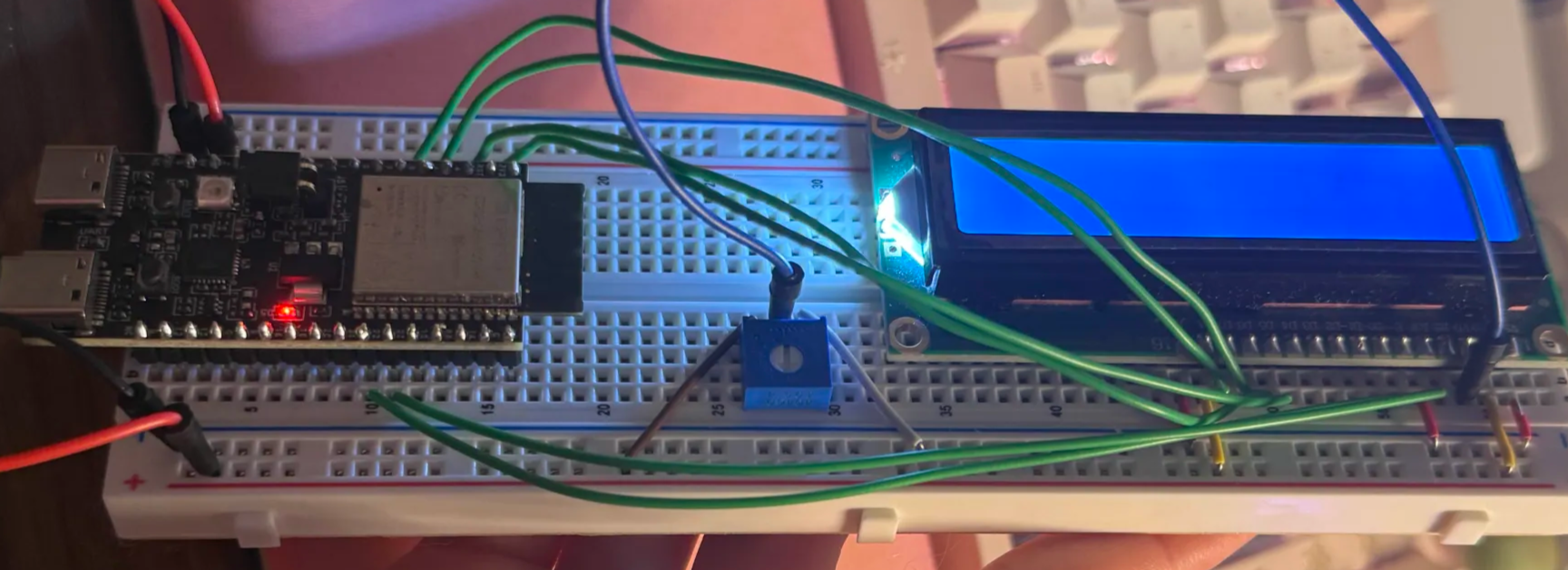
Breadboard of the LCD, tested with the ESP32
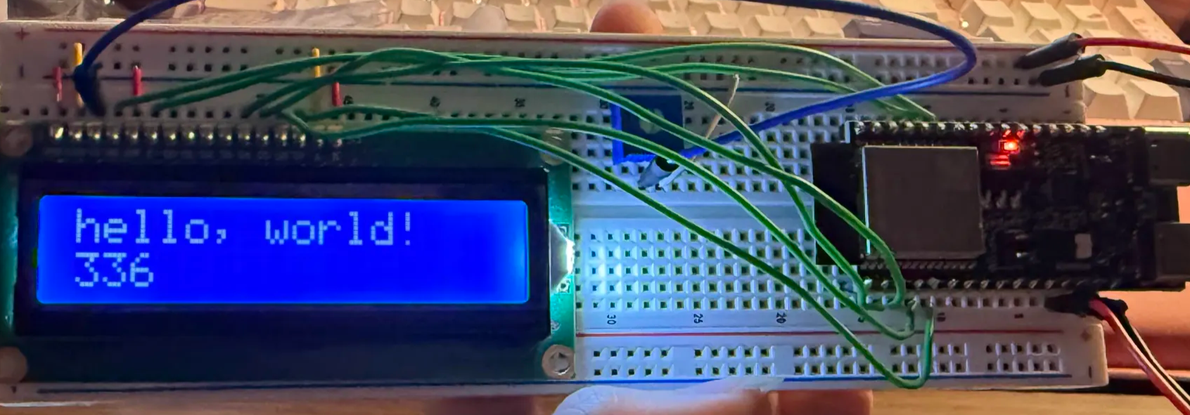
Test of software on LCD by printing "hello, world!" on first row and the number of seconds since setup on the second row
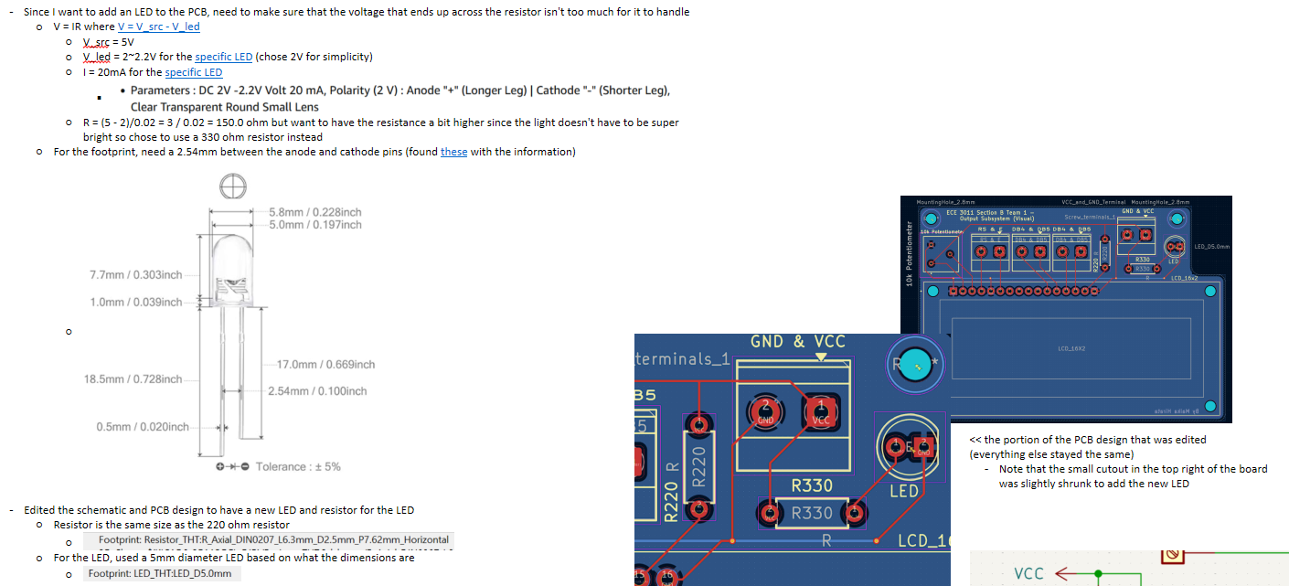
Schematic and PCB Design
PCBs for the LCD and speaker were created to be small to fit on the car, utilizing vias for the GND connections. The PCBs were then fabricated through JLCPCB.
LCD schematics and PCB designs
There were two different iterations of the LCD schematic and PCB design. One utilizes levelshifters which were meant to ensure a consistent 5V since it was unclear before fabrication if the ESP32 could provide consistent enough power. This ended up being unnecessary, but the design was fabricated just in case. Both iterations can be seen in the slideshow.
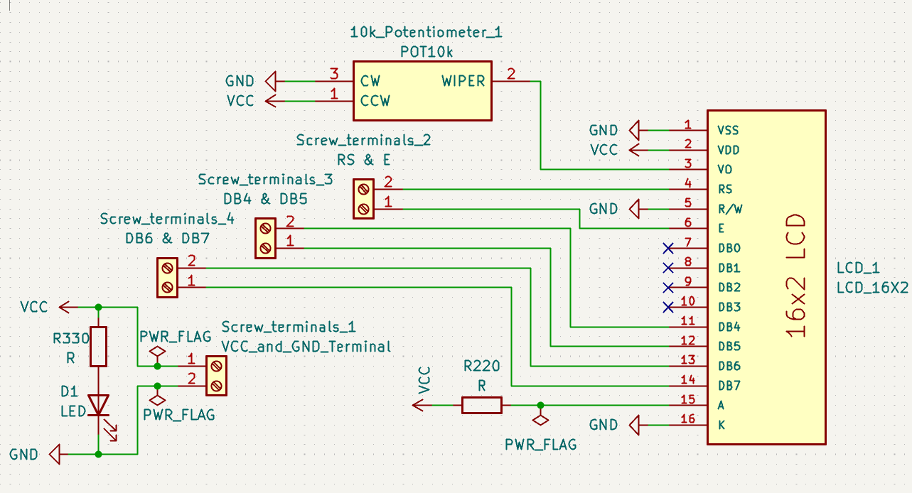
Final, utilized LCD schematic design
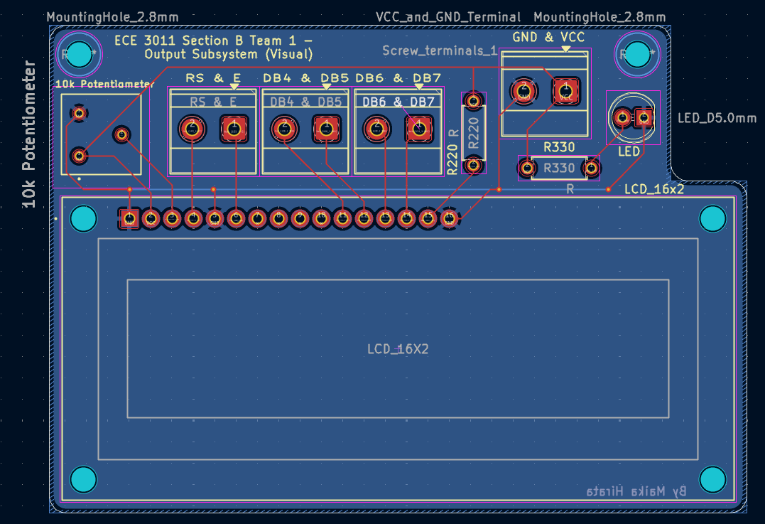
Final, utilized LCD PCB design
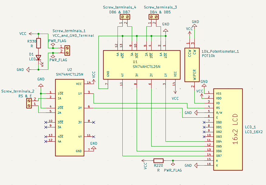
Iteration of the LCD schematic design with levelshifters

Iteration of the LCD PCB design with levelshifters
Speaker schematics and PCB designs

PCB design for the speaker
Due to the simplicity of the design, there was only one iteration of the speaker PCB and schematic, both of which are seen here.
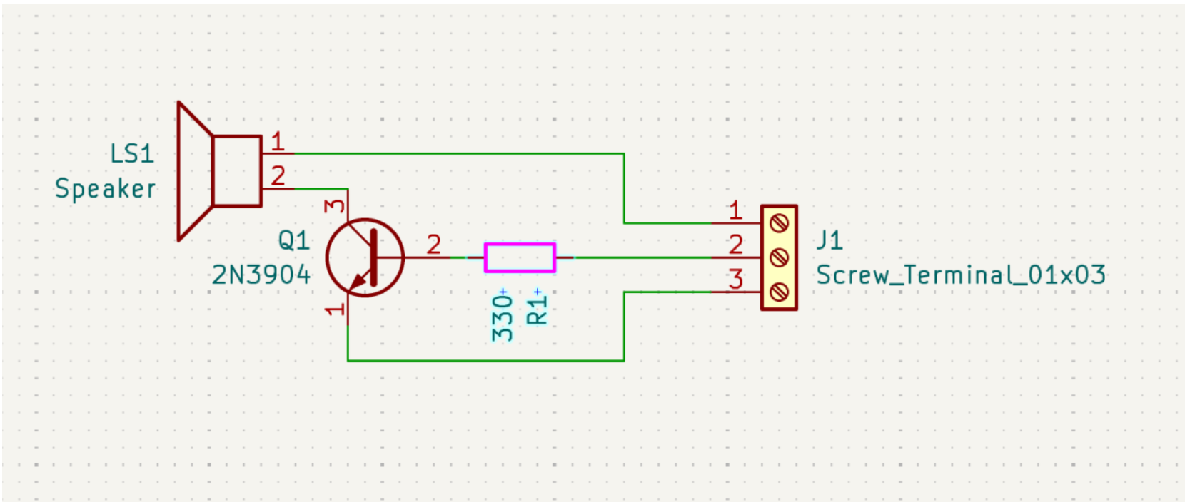
Schematic of the speaker
PCB Soldering and Testing
After PCBs were fabricated, they were tested through the following procedure:
- Check for any visible errors (e.g. shorts, missing traces, etc.)
- Use a multimeter and do a continuity test
- Solder on small components (e.g. resistors) and do another continuity check with the multimeter
- Solder on the LCD and the speaker and do another continuity check with the multimeter
- Power on the PCBs and check for any abnormal occurences that would indicate something's wrong, like a burning smell
- Test the functionality of each PCB
Integration
The LCD PCB was connected after the sensing and motion subsystems were deemed to
function together well, which means that the sensing values were influencing whether
the car was turning or going straight. The LCD being added was to show this
information to the user. After the LCD was displayig the correct values and the car
was turing as needed based on sensor values, then the speaker was added.
The speaker code was meant to run the entire time the car was in motion, so
threads were used, where one thread was for the speaker and the other thread was for
the sensing and motion code. This code worked successfully to allow the car to run
while the audio was also playing.